Held Open Limit Switch Wiring Diagram For A Nc
- Wire the relay according to the diagram above 12V Relay Wiring - Connect T3 and T7 to the positive terminal 12V of your power supply - Connect T4 and T8 to pin 8 of the relay - Connect the positive side of the actuator red wire to pin 5 of the relay - Connect the negative side of the actuator black wire to pin 6 of the relay. Mechanical limit switches are contact sensing devices widely used for detecting the presence or position of objects in industrial applications.
 Industrial Instrumentation And Automation Key Components Used In Industrial Control
Therefore each limit switch Black 3-pin connector plugs into the header with the Green wire to the upper pin and the Black wire to the lower pin.

Held open limit switch wiring diagram for a nc. Sometimes the contact point a is called NO contact point and the contact point b is called NC contact point however the JIS C 0301 Graphical Symbols for Diagrams prescribes them as contact point a and contact point b respectively. Yes a NC contact should be safer for an end switch a bad signal switch fails open circuit. Held Open Limit Switch Wiring Diagram For A Nc - Presented at the site to sell electronic manual New Idea is a comprehensive directory that contains the catalog of spare parts for agricultural machinery company New Idea repair manuals maintenance manuals technical specifications special instructions additional information on maintenance and repair services agricultural New Idea AGCO.
The main function of the limit switch is to open or close an electric circuit when the physical limit of the operation of the controlled device has reached. Open NO If the moving part of a limit switch symbol is drawn above the terminal connections is the switch NO or NC. The push button is actuated by hand whereas the limit switch is operated mechanically.
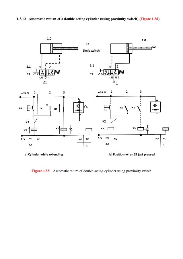
Read Or Download The Diagram Pictures Open Limit Switch Wiring Diagram For For FREE A Nc at CROWDFUNDING-PLEDGEDEMOAGRIYACOM. In both examples the load being driven by each proximity switch is a light-emitting diode LED. I would recommend wiring the E-Stop to an input terminal via an NC connection.
Read Or Download The Diagram Pictures Open Limit Switch Wiring Diagram For For FREE A Nc at CROWDFUNDING-LENDDEMOAGRIYACOM. The limit switch is like a 1 NO 1 NC push button. The term limit switch is derived from the operation of the device it-self.
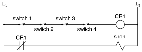
Normally Closed NC but held open. The lamp will energize only if someone presses the switch holding its normally-open contacts in the closed positionNormally-open switch contacts are sometimes referred to in the electrical industry as form-A contacts. As an object or target makes contact with the operator of the switch it eventually.
A limit switch is used to control electrical devices by breaking and completing electrical circuits. The following schematic diagrams contrast the two modes of switch operation using red arrows to show the direction of current conventional flow notation. The power input terminal is called the common terminal and is used to connect the switch to a power source.
When wiring limit switches to the breakout board generally NC Normally Closed are connected in series acts like a wire that when broken breaks the circuit. SUBSCRIBE NOW FOR MORE AWESOME METAL FABRICATION VIDEOSA simple breakdown of how a normally open switch NO should operate vs how a normally closed switch. NO Normally Open is generally wired in parallel where if one is pressed the wire creates a circuit connecting the pin to gnd.
A limit switch is used to control electrical devices by breaking and completing electrical circuits. What is a symbol. The limit switch is wired normally open but maybe the cylinder that actuates it is retracted in its normal condition which closes the switch therefore it is normally open held closed.
A graphic element that represents a quantity. The relay is what latches the motor on when the weight reaches a low closing a no normally open limit switch. Proximity Switch consists a sensor circuit and a driver circuit.
Roller for less friction and a more precise end position. If the moving part of a limit switch symbol is drawn below the terminal connections is the switch NO or NC. It is abbreviated COM The other terminals are the normally open NO.
Held Open Limit Switch Wiring Diagram For A Nc - Ford 9N2N Wiring Diagram Starter Assy. It requires a NC Normally connected circuit for the machine to be operational and when the circuit breaks the machine shuts off. We can tell this switch is a normally-open NO switch because it is drawn in an open position.
This is the industry standard. The Green wire is the common of the switch and the Black is the normally open contact. So it youre looking at the pneumatic diagram or testing things with the machine in its normal position then the limit switch would be closed.
I use 3-pin microswitches NO and NC with roller-lever for that ebay. The wiring diagram above is similar to the ones shown earlier. It has three terminals.
The open pin Red wire on the Black 3-pin connector is left unconnected. 12V CONVERSION a la Tisco where ammeter reads ONLY alternator Takitii retrofit tensioning bandjspring kit Note. Reversing motor circuit with limit switches ahmad khattab.
Connect the NC normally closed to a digital pin and the CO common to ground.

 Pushbutton Switches And Types Of Switches Instrumentation Tools

 Learn Cnc Ladder Logic Cnc Controls Learn Plc Programming And Plc
 Held Open Limit Switch Wiring Diagram For A Nc 2003 Engine Diagram For Wiring Diagram Schematics


