Eaton Drive Wiring Diagrams
I cannot copy programming between an 9000X AF drive and an HVX9000 AF drive. Route the zone interlock wiring separate from power conductors.
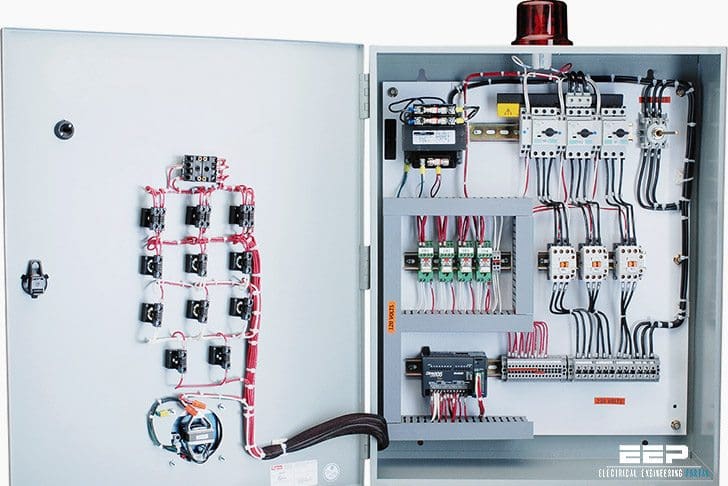 Basic Wiring For Motor Control Technical Data Guide Eep
Samsung lithium-ion battery 136S installation manual for end customer.

Eaton drive wiring diagrams. Figure 1 is a typical wiring diagram for a three-phase mag-. SVX Series Adjustable Frequency Drives. Demand more energy efficiency.
If the wiring diagram cant be found from above methods please contact the TRC Distribution team for assistance in identifying the frame size. MVX9000 Adjustable Frequency Drives Open Drives Table 3. Here you can find the latest products in different kinds of eaton fuller 13 speed air line diagram.
9000X AF Drives User Manual MN04001004E For more information visit. We are dedicated to providing fast friendly and accurate assistance. Drive Coupler alignment tool must be used when installing Drive Coupler contact your Eaton Liaison Engineer for align-ment tool print.
Flywheel Coupler Alignment Shaft. Be responsible to the purchaser or user in contract Standard Wiring Diagrams and Terminal Locations. 13 speed eaton fuller transmission diagram eaton 18 speed how to change to an old style a4487 shift knob.
They can be used as a guide when wiring the controller. Casting 113702 is on the back housing. English US 3-Sep-2020 6045 kB.
Eaton 2 speed axle wiring diagram. Drive axles drive axle assembly tag 1. Or Eaton Electrical Inc.
HVX9000 AF Drives User Manual TD04008003E For more information visit. Control Terminal Wiring Factory Settings Applicable Motor Braking Resistor Kit PN Qty of Resistors in Kit Wiring Total Resistance and Wattage applied to MVX Full Load Torque kgf-m of System Braking. That is why we offer you so many ways to get the support you need.
Learn all about 2 speed axles including how they work proper operation and proper maintenance. This innovative VFD series comes standard with an industry-leading energy optimization algorithm high short-circuit current rating and a robust design that offers increased efficiency safety and reliability. All Braking Resistors Braking Units Used in AC Drives Wiring Diagrams Figure 1.
Eaton top wiring kit for UL9540a battery cabinet installation instructions. Samsung lithium-ion battery 128S installation manual for end customer. You can search for most wiring diagrams on our website by entering the wiring diagram number in the search field.
They show the relative location of the components. Twisted together AWG 14 to 20 copper wire. Eatons PowerXL DH1 variable frequency drives are designed to significantly reduce energy consumption and increase cost savings for HVAC applications.
DO NOT GROUND any zone interlock wiring. Are transformer wiring diagrams available on your website. Standard Wiring Diagrams and Terminal Locations Power and Motor Wiring Terminal Schematic for SVX9000 Drives SVX9000 Power and Motor Wiring for Low Horsepower Drives 1 30 hp UV W B M 3 L1 L2 L3 L1 L2 L3 B- R- T1 T2 3 External RFI-Filter Optional BR Optional External Filter Optional BR Power Board 230V 1 15 hp 480V 1-12 30.
Andor Eaton Corporations Eaton experience and judgment and may not cover all contingencies. It says fail then SVCHST-05. This manual includes information on two types of shift sys tems currently in use.
The maximum distance between two farthest breakers on different zones from the Z out downstream to the Z in. Need a wiring diagraphm for cooling fan circuit in Frame 10 300HP SPX9000. Wiring diagrams sometimes called main or construc-tion diagrams show the actual connection points for the wires to the components and terminals of the controller.
English US 5-Oct-2020 6186 kB. New EatonFuller RTLO20918B 18 speed Transmission 20918B 18 speed roadranger airline scematics diagram answered by a verified technician. Torque to 35-40 lbs-ft.
Install the Drive Coupler using 12 Hex head capscrews wi th lock washers 38-16 X 1¼ SAE grade 5 minimum. The 2 speed box is a three bolt two wire arrangement. SPX Series Adjustable PowerXL SeriesDG1 Control Wiring Diagram.
 Contactor Wiring Diagram With Timer Diagram Diagramtemplate Diagramsample Well Pump Pressure Switch Electrical Wiring Diagram Wire
 Contactor Wiring Diagram With Timer Unique Eaton Contactor Wiring Diagram Wiring Diagrams Schematic Diagram Timer Eaton
 10 Ford L8000 Truck Wiring Diagram Truck Diagram Wiringg Net Diagram Ford Ford Truck
 Polaris Predator 500 Wiring Diagram For Polaris Ranger Diagram Ranger
 Unique Single Phase Capacitor Start Capacitor Run Motor Wiring Diagram Electrical Wiring Diagram Electrical Circuit Diagram Compressor


